Showing posts with label Arduino. Show all posts

Thursday, March 17, 2016

Pi vs Arduino vs NodeMCU vs ???

It's official - the Internet of Things has a lot of, um... things. So many options! Consider this: my friend and I are working on a weather station. Of course, it can't just be a simple weather station, it eventually needs to be a cluster of stations that can be used to measure differences in micro-climates. More on that later, LOL.

The initial goal is to put a weather station on a roof, without wires. With so many little devices, the question is simple: which is the right device for the job?

  • I started in on this the other day when I started messing around with the GPIO pins on the Pi. In about 10 min, I was reading in temp and barometric pressure data and thought "Dang, that's easy!". The Pi is awfully powerful and, now with the Pi 3, wifi-enabled.
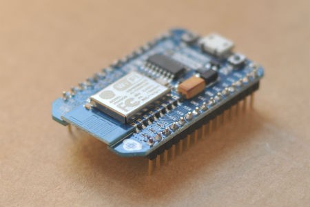
  • And then there's NodeMCU. Very cool little wifi-enabled device that can take signal on a variety of analog, digital and serial-dedicated pins. And then it can run Lua to actually form that data into "IoT" capable packages, like HTML pages or JSON packets. Finally, it can be a rudimentary http server, so data can be retrieved (conversely it could be written as a client, to push data directly into the cloud). Seemed to me to be the perfect solution.
  • My friend Chuck is a strong advocate for using the Pi with an Arduino on a Pi alamode board. The arduino collects the data, the alamode board pushes that data into the Pi, and the Pi processes it.
My take? I see four viable solutions for getting the data off the Sparkfun weather shield and into "a consuming sink" such as the cloud, a data aggregator like a database, or published to the web.
  1. Weathershield to Pi via GPIO interface
  2. Weathershield to Pi via Arduino
  3. Weathershield to NodeMCU
  4. Weathershield to Arduino with WiFi chip
Each solution has advantages and disadvantages, and that's what we're doing to explore now.

Weather Shield to Pi via GPIO

This is an elegant solution - it requires the Weather Shield, some connecting wires, and a Raspberry Pi. It's elegant in that there are few moving parts - wire it up, good to go. Right? Wrong. Not all of the Weather Shield components seem to have Python libraries available, which means the coding would need to be done in C. Not impossible, but not necessarily straightforward.


Acquisition cost: 
  • Weather Shield: $39.95 + shipping
  • Raspberry Pi 3: $35.95 + shipping
  • Misc parts: $5
  • Total: $80
Development effort:
  • Moderate to high

Weather Shield to Pi via Arduino

This is the easiest solution to build, frankly. The weather shield runs great on the Arduino, all sorts of libraries and sample code abound on the Internet. 

Acquisition cost:
  • Weather Shield: $39.95 + shipping
  • Raspberry Pi 3: $35.95 + shipping
  • Raspberry Pi Alameda: $35.00 + shipping
  • Misc parts: $5
  • Total: $115 + shipping

Weather Shield to NodeMCU

By far the most elegant solution, holy cow... Suspend disbelief briefly and take a walk with me... You have a weather station on the roof, which feeds data into a Sparkfun weather shield. That shield, in turn, feeds data into a NodeMCU chip - tiny, quarter-size chip with wifi on it. The NodeMCU does three things: 1) it pushes the data to a cloud service, every N minutes; 2) it serves the data up via JSON string to anyone on the local network, and 3) it serves up data via formatted HTML on the local network. Awfully cool, and the cost? Nominal.


What's the issue? Simple - the libraries for the components of the weather shield only exist in part, and it's a process of porting them to Lua to make them work. The other problem: NodeMCU only has a single analog pin, whereas the weather board uses three or four.

--> Caveat: the NodeMCU *can* be programmed via Arduino, using Arduino libraries. I need to look into this more; not sure if there's enough memory to do it, though. And the Arduino environment has convoluted support for outputting HTML. I think I just need an afternoon to figure it out though. But still, the bottom line is it's not the right tool for this job.

Acquisition cost:
  • Weather Shield: $39.95 + shipping
  • NodeMCU: $15.00 + shipping
  • Total: $55 + shipping

Weather Shield to Arduino with Wifi Chip

This solution is honestly just a variant on the above solution - the weather shield speaks to an Arduino (great library support) and the Arduino uses a Wifi chip on a shield to publish the data. 

Slightly more expensive than the standalone NodeMCU solution:
  • Weather Shield: $39.95 + shipping
  • Arduino Uno $24.95 + shipping
  • Ada fruit Huzzah wireless shield: $39.95 plus shipping
  • Total: $105 + shipping

Summary

The cheapest possible solution, using the Weather Shield with NodeMCU, is not possible because NodeMCU only has a single analog pin and the weather shield needs multiple. That doesn't mean NodeMCU isn't a useful tool - I have a couple of other projects it might be perfect for. It does mean, however, that it's the wrong tool for this job.

From a financial perspective, the lowest cost solution is the Weather Shield plus the Raspberry Pi. It presents some problems - probably not insurmountable, but there'll be some effort to integrate the Weather Shield natively into Pi via Python or C. The time spent may not be worth the money saved over the alternatives (which both make use of an Arduino to read and interpret results).

So a little research is needed, to see how well the Pi can work with the Weather Shield's components. That's how to solve this specific application, but making a global rule overall? Globally I think it's easy to say that the NodeMCU is a low-cost solution but will almost alway have a steep implementation curve, at least until the dev community matures and catches up with Arduino. Overall from a sheer convenience perspective, the best solution is either 1) Arduino with Pi or 2) Arduino with wireless.

Bottom line: my buddy Chuck is right. When I insisted I take some time to look into building this solution with something other than Arduino, he told me I was wasting my time. I *was* right in that it would be more elegant, but he is right from a practical perspective. Everything is just "there" and ready to use, if Arduino plays a role in the solution.

Tuesday, November 11, 2014

Ultimate Telemetry Platform

I have been working for the past 4 years, off and on, on building the ultimate telemetry platform for rockets and balloons. I started originally with a set of stackable Arduino shields - GPS, SD card, etc. Over the years my understanding has grown and the technology has shrunk quite a bit, to the point where I've designed what I think to be the ultimate platform.

Ultimate Telemetry Platform

The ultimate platform consists of:
  1. Arduino Mega
  2. Mega proto shield
  3. Adafruit "Ultimate GPS" breakout
  4. Adafruit microSD breakout
  5. Adafruit 10 DOF IMU
  6. 2m amateur "radio on a chip"
  7. 3.3v power supply
I liked the Mega because of the extra size. My vision is that my local Scout troop will start a NOVA team and that the kids will throw additional experiments onto the telemetry platform, and the Mega gives me plenty of pins!

Thanks to my employer, Caliber Security Partners, I was able to stock up on supplies for the project:


Arduino Uno, Mega, and the breakout boards.

My original design focused on ballooning, but I ran into an opportunity to launch the telemetry platform via a rocket. My buddy and amateur radio "Elmer" has a high-power rocket with a payload. Perfect for the Mega!

Here's a shot of the Mega proto shield with the breakout boards:

Mega proto shield with the GPS and IMU. Radio chip and power supply will go in the empty spot on the left.


With the radio chip and power supply, there's not enough acreage for the microSD card, so I put it on the bottom!


This tangle of wires is the 3 sensors on a breadboard, tied to an Uno


Life Is Full of Opportunity

I ran into a number of issues building my platform:
  • My buddy had to back out - no motor, his high power license expired, and he's out of time.
  • The radio and power supply haven't arrived
  • The microSD card draws too much power to use without an external power supply
  • ...
So now I have an opportunity! My launch is scheduled for 11/15, and it's 11/11 today. I have to build a solution practically overnight.

Options

Launch Platform

I have an old Estes "Maxi Force" 3-motor cluster rocket that I can launch with. It wasn't made for payloads, so I'm taking a bit of a risk here but at this point I am going to go for it. The nose cone is just exactly wide enough to fit an Arduino Uno:

It's this, or we launch with a kite (and the kite's not all that exciting, especially since we're launching rockets the boys built as part of Space Exploration merit badge).

Telemetry Package

I have a few options on the telemetry side:
  • Powered Arduino sd shield, with is big and bulky
  • Strip out the GPS and send up the microSD shield and the IMU on an Uno
  • Do the same, but use a PC board and solder on a nano
The next few hours will be telling, as I hook the Nano up to the breadboard to see if it can handle everything. I have a number of 3.3v batteries from various cell phones, so I think I can actually use them to power the microSD card. If the nano idea pans out, I just need to find enough power to bring up the Nano and the sensors.


Saturday, September 20, 2014

Rocket Repairs

I was hanging on with my Elmer Chuck (WB6YOK) the other day and the conversation turned from radios to radios in balloons. We have been "working on" a balloon project for what, five years now? We started in with Arduino several years ago and, while we haven't launched anything yet, we've got solid plans and a lot of functioning code for various sensors. As we were talking about the balloon project, I mentioned that I am interested in starting a BSA Nova program (BSA's new STEM initiative, to encourage youth to study science, technology, engineering and math). I told him that we are doing space exploration merit badge in Novemeber and mentioned that I would like to launch a rocket at October's Jamboree on the Air campout, to start to generate some interest.

Well, as it always does, the conversation quickly devolved into some wild fantasizing about having a rocket that was large enough to carry the balloon payload, so we could test it. As we were discussing that, Chuck said "Hang on, wait a minute..." and left the room. He returned with an enormous 3-peice rocket (base, payload bay, and nose cone). "This ought to do what you want," he said. Turns out, Chuck is high-powered certified. This is the rocket he certified with--it's powered by a single "H" motor and should go as high as 8,000 feet or more. 

As we talked further, I got more excited about the possibilities. That rocket could carry an Arduino, a Pi with a camera--pretty much anything! Suddenly Chuck left again and returned with this rocket:


An Estes Maxi-Force 3-engine cluster 50" tall rocket. These were a short-lived rocket built by Estes in the early 80's. Chuck said "It's yours if you want to fix the fins." Well, gosh... How difficult could that be? I took it before he could change his mind! 

Two out of three fins needed repair. The first had several cracks lengthwise, and the second had lost its leading edge. Today's project was to swing by Hobby Lobby after my trail run, to grab a few motors and some balsa wood, and then to fix the fins.


These are the cracks on the first fin (above).


And this is the broken leading fin. 

The fins are made of several peices: the main or base fin, a leading fin above it, and some edging which appears to be made of tougher material to withstand the bumps of landing.

My first plan was to just rip all three fins off and replace them with laser cut plastic fins (another buddy has a laser cutter). The more I thought about that, though, the more I realized it was more work than it's worth. As I looked over the fins again, I realized they were totally fixable. I needed to trace one of the leading fins to make a pattern to cut a new one from balsa, and I needed to glue the cracks together on the other. 

So today I dropped by the store and picked up balsa. After a few chores, I started in. First I opened up all the cracks in the fin, as shown below:


Then with a toothpick, I started to slip Gorilla Glue into all of the cracks. It's not as precise as I would like to be, but it worked. Here is the fin, drying, with a little pressure supplied by a couple rubber bands:


Next I traced an intact leading fin, cut some balsa, and dry-fitted a new leading fin. First I had to carve away the remainder of the leading fin--it isn't perfect, the surface of the rocket body was a bit wavy when I finished but the glue will help with that. Balsa is a really forgiving medium, and the dry-fit went quickly.

Knowing that it would be a challenge to have the new leading fin attach at every point and stay aligned, I opted to only glue where it touches the base fin and where it contacts the rocket body nearby. Once it's dried, I will glue up the rest. It's that easy...

I had to laugh--I spent more time thinking up a variety of ways to replace the fins than I actually spent repairing them. In fact, I've spent more time writing up this blog entry! With only an hour's effort, everything is glued except the front of the leading fin.

My next steps are to sand out the excess Gorilla Glue, then using a light putty I will fill in gaps and holes. Once the fins are smooth and straight, I think I'll paint the base again--probably black, just to put my own touch on the rocket.

The Scouts don't know about this rocket, but this is the one we will launch at JOTA, in an effort to pique their interest. I think it'll get their attention!

If I had unlimited time and funds, I would put together a tiny XBee unit, with an XBee 2 transceiver and a GPS. Then I would find a way to slip that into the nose cone so we could stream telemetry while flying the Maxi-Force. But I decided to keep my focus on building a package for the November launch, instead.

Sunday, August 24, 2014

Arduino: TempLogger

I’ve gotten terrible sleep the past 4-5 weeks. I wake up every night around 2 am, just hot and uncomfortable. I usually can’t get back to sleep once I wake up, either.

So time for another lifehack! I have an Arduino, I have an SD card logging shield, and I have a digital temp sensor – I decided to build a temperature logger and record the temps overnight.

WP_20140824_001[1]

Below is the code from my first attempt about a year ago. I broke it out again today and was looking at it – I found an article on the BMP085 online at Sparkfun, which when reading seems to indicate that you need to do a fair amount of calibration at startup in order to get accurate data. I went ahead and downloaded Sparkfun’s code and ran it – lo and behold, with all of its calculations it is still reporting the same 80 degrees my simple code is reading.

Lesson: you don’t need that calculation!

#include <Wire.h>
#include <Adafruit_BMP085.h>
#include <SD.h>
#include "Arduino.h"
#include "RTClib.h"

/**********************************************************************************
   TempLogger is an Arduino tool to log temperatures throughout a sustained time
   period. Ever wonder how well your heat is regulated? Tired of waking up hot at
   night? That's why I built templogger - my bedroom seemed awfully hot around 2
   am and, coincidentally, I kept waking up at 2 am.
  
   Requires an Arduino board, a GPS logging shield, and a BMP085 pressure/temp
   sensor from AdaFruit (
https://www.adafruit.com/products/391)
  
   See K7JTO.blogspot.com for this and other Arduino recipes.
**********************************************************************************/

/*
  Connect VCC - 3v
  Connect SCL - Analog pin #5
  Connect SDA - Analog pin #4
  Connect GND - GND (obviously)
*/

// Define Section
#define DEBUG 1                                    // Toggle 1/0 to en/disable serial out
#define led1Pin 5                                  // OPTIONAL: wire pin 5 to write LED
#define led2Pin 6                                  // OPTIONAL: wire pin 6 to read LED
#define BUFFSIZE 90                               // Create a buffer to store log file name

// Variables and Objects
Adafruit_BMP085 bmp;                                // ID for BMP085 unit
RTC_DS1307 RTC;                                     // Real-time clock object
const int chipSelect = 10;                          // Must be left as an output or SD library won't work
boolean gotSDCard = false;                          // Set to true if file successfully created
File logFile;                                       // File for logging data
char buffer[BUFFSIZE];                         // String buffer for the sentence
uint8_t i;                                          // usigned int for iterating
float currTemp = 0;                                 // Int for current temperature
String stringTemp = "";                             // String to hold temperature in
static char sprintfbuffer[15];                      // Buffer to convert float to string
static char dtostrfbuffer[15];                      // 2nd buffer to convert float to string


void setup() {
  Serial.begin(9600);
  if (!bmp.begin()) {
    Serial.println("Could not find a valid BMP085 sensor, check wiring!");
      return;
  }

  // Setting up the card means creating a new logging file for
  // each session, and initializing that logging file.
  if (setupSDCard()) {
    if (DEBUG) {
      Serial.println("card initialized.");
    }
    // Start RTC
    RTC.begin();
  }
}
 
void loop() {
  // Variables
  String nowTime = "";                                // String name for current time
  String dataString = "";                             // Store line for temp sensor
   
  // First grab the time from the RCT on the logging shield
  DateTime now = RTC.now();
 
  // Now build the timestamp. Should look like 12/25/2013 04:27:00"
  // Slight hack - sometimes the seconds value reads funny, and for
  // what we're doing, seconds aren't important, so just shove two
  // 0's in.
  nowTime += now.month(), DEC;
  nowTime += "/";
  nowTime += now.day(), DEC;
  nowTime += "/";
  nowTime += now.year(), DEC;
  nowTime += " ";
  nowTime += now.hour(), DEC;
  nowTime += ":";
  nowTime += now.minute(), DEC;
  nowTime += ":00";
 
  // Next grab the temp from the BMP. Problem is the temp comes in as an int, which
  // the Arduino can't convert to a string. So once the temp comes in, turn it into
  // a string via sprintf and dtostrf
  currTemp = ((bmp.readTemperature()*1.8)+32);
  sprintf(sprintfbuffer,"%f", currTemp);
  dtostrf(currTemp,8, 2, dtostrfbuffer);
 
  dataString = nowTime + "," + dtostrfbuffer;
  if(DEBUG) {
    Serial.println("Datastring: ") + dataString;
  }
   
  // Now write temp to logfile
  File dataFile = SD.open(buffer, FILE_WRITE);
   
    // if the file is available, write to it:
    if (dataFile) {
      // Light an LED
      digitalWrite(led1Pin, HIGH);
      digitalWrite(led2Pin, HIGH);
     
      // Write
      dataFile.println(dataString);
      dataFile.close();
     
      // Unlight the LED
      delay(1000);
      digitalWrite(led1Pin, LOW);
      digitalWrite(led2Pin, LOW);
     
      // print to serial port too:
      if (DEBUG) {
        Serial.println(dataString + " saved to data file");
      }
    }
    else {
      Serial.println("Error opening log file to write " + dataString);
    }
   
   // Now delay the device. This could be a sleep delay, if the device were running off
   // batteries, but a simple delay will suffice for externally-powered scenarios.
    delay(60000);
}

//** Sets up SD card. Returns true if no error **/
boolean setupSDCard() {
  // Now set up SD for logging
  // This code lifted from "Datalogger" sample sketch
  if (DEBUG)
    Serial.println("Initializing SD card...");
// make sure that the default chip select pin is set to
  // output, even if you don't use it:
  pinMode(10, OUTPUT);
// see if the card is present and can be initialized:
  if (!SD.begin(chipSelect)) {
    Serial.println("Card init. failed! chipSelect = " + chipSelect);
    error(1);
    return false;
  }
  // Now create a unique file. NOTE: IF YOU CHANGE THE FILE NAME, CHECK THAT YOUR INDEXES STILL WORK
  // (buffer[6] and buffer[7] will need to change if you change the length of the file name)
  strcpy(buffer, "TMPLOG00.TXT");
  for (i = 0; i < 100; i++) {         
    // Keep iterating till you find unique file name
    // Create if does not exist, do not open existing, write, sync after write
    buffer[6] = '0' + i/10;
    buffer[7] = '0' + i%10;
    if (! SD.exists(buffer)) {
      break;
    }
  }
  // Now open the file just created
  logFile = SD.open(buffer, FILE_WRITE);
  if( ! logFile ) {
    if (DEBUG)
    {
       Serial.print("Couldnt create "); Serial.println(buffer);
    }
    error(3);
    return false;
  }
  if (DEBUG)
  {
    Serial.print("Creating file on card: "); Serial.println(buffer);
  }
  return true;
  // Done opening log file
}

// Handling Errrs HERE
// blink out an error code
void error(uint8_t errno) {
  if (DEBUG)
  {
     Serial.print("Error encountered. Error no: ");
     Serial.print(errno);
  }
 
  // First, blink 3x fast
  blinkThrice();
 
  // Now blink errno times, slow
  for (i=0; i<=errno; i++) {
    digitalWrite(led1Pin, HIGH);
    digitalWrite(led2Pin, HIGH);
    delay(3000);
    digitalWrite(led1Pin, LOW);
    digitalWrite(led2Pin, LOW);
    delay(1000);
  }
 
  blinkThrice();
}

void blinkThrice() {
  for (i=0; i<3; i++) {
    digitalWrite(led1Pin, HIGH);
    digitalWrite(led2Pin, HIGH);
    delay(3000);
    digitalWrite(led1Pin, LOW);
    digitalWrite(led2Pin, LOW);
    delay(1000);
  }
}

/***************************************************
  Portions of this code based on Adafruit BMP085 sample code. See
  info below.

  Designed specifically to work with the Adafruit BMP085 Breakout
  ---->
https://www.adafruit.com/products/391

  These displays use I2C to communicate, 2 pins are required to interface
  Adafruit invests time and resources providing this open source code,
  please support Adafruit and open-source hardware by purchasing
  products from Adafruit!

  Written by Limor Fried/Ladyada for Adafruit Industries. 
  BSD license, all text above must be included in any redistribution
****************************************************/

Sunday, March 10, 2013

TrunkTrackerino

It's simple, really:
I have teens...
They drive my car...
They are boys...
I am an engineer...
I like life hacks...
I have an Arduino...
And a GPS logging shield....

Therefore, TrunkTrackerino.

More than two years ago I started a push to get my Arduino working with the GPS logger shield. It failed, mostly because I had some other life pressures. I recently pulled out my Arduino and started messing with it again, not really sure why... And I got the GPS working. And then I thought... I can build a simple device to throw in the trunk that will record driving speed! And thus TrunkTrackerino was born.

There are sketches for using a GPS. There are also sketches for logging GPS data to a card reader. But I really didn't like any of them individually, so I have merged them together. And as of today, I believe I have it working (not entirely sure, since I'm in my hotel and can't pick up signal--I will know more tomorrow).

The goal is to build an Arduino-based device which
* tracks speed and location
* sleeps when there is no motion
* logs nothing when there's no valid data
* stores data on an SD card
* can be imported into XL to view historical speed data
* can be imported into Google Earth for bread crumb data

Eventually this project will end up as the base for the APRS balloon tracking system. For now, it's enough to know my boys are as honest as they say they are.

Update: I took a brief stroll around the hotel entrance today. For some reason, the logging code is logging an empty file. The GPS is working great--when I watch in Arduino's serial monitor, I can see good valid strings which are being parsed great. I'd say I'm 10 lines of code from a working beta.