Sunday, August 17, 2014

Balloon–Question, more questions…

I’ve mentioned a couple times on my blog that I’m interested in building a high-altitude balloon and sending some experiments up. I have worked for several years now on an Arduino-based package. I’ve successfully got GPS tracking working, SD cards, and a variety of sensors.

Now I’d like to take the next step and actually start transmitting sensor data over RF (preferably VHF or UHF). I see a lot of balloons going up with Trackuino-based comms, but I’ve also been intrigued with the Radio Shield 2 from Argent communications.

There are a ton of options—there are even folks sending photos back via radio layers. I haven’t found a really good primer yet for all the various options, but I’m getting started.

More to come…

Tuesday, August 12, 2014

SDR on Linux Mint

I picked up one of those "el-cheapo" SDR dongles off Amazon recently and got it working on Windows with SDR Sharp. I'm actually kind of happy with it - not enough time to do a lot, but it's a start. Of course, my Windows machine is my day-to-day work machine and SDR# uses a lot of resources. So why not move it to linux?

My Linux box runs Mint 17 (this will be important very soon). I poked around the Software Manager and was surprised that searching for "SDR" returned no results. I did a few interwebz searches and came across an excellent guide to using SDR on Linux--which included a full bash script for downloading and building GNU-Radio. Seeing that it *is* the workday, I figured that's probably better than doing it manually!

OOPS - when I tried to run the bash script, it alerted me that I need at least version 11 of Mint. But wait - like I said, I'm on Mint 17. I did a little troubleshooting by opening the script and found out the supported versions of Mint are hard-coded to 11, 12, 13, 14, and 15. So I did what any good hacker does and I simply added 17 to the list:


Bazinga! The script is now running.

In total, with me focusing on my business day, the script ran for about 5 hours (part of that was the script waiting for me to enter my password for "sudo" dependent actions).

Saturday, July 19, 2014

Buddistick Hiking Stick Mount

 I am a weight geek,a specially when I'm hiking. I bought my Buddistick so I could operate backcountry QRP even when I'm about tree line, but I've been stumped looking for a leightweiht weigh to get it vertical. I finally figured something out, and with the help of my Elmer, refined the design today. I'm quite pleased with it, in fact.

The design begins with a 1" PVC cap with a 1/4-20 bolt through the top. I then modified the Buddistick base plate by adding a 1/4 hole, so there are 5--1 off each corner (used for guy lines) and one on the center of one end, for the counter poise. Now the hiking staff I use all the time (which I made myself from a Virginia maple sapling on my property) can serve a second purpose.

The design did great in this evening's calm weather. I'll be taking it up a local peak in a few weeks, so we'll see how it does in a breeze.


Tuesday, May 27, 2014

Mini DXPedition

My buddy WB6YOK and I have been toying with a semi-local mini-DXPedition. I brought up the hair-brained scheme last fall and we’ve dabbled at it here and there ever since. We decided to do something to commemorate the air mail arrows from the US Airmail service dating back to the 20’s. We found an arrow about 125 miles north of Salt Lake City, just across the border in Idaho. This Memorial Day we took a road trip to check out the site.

Airmail Arrows

In the 1920’s the Postal Service wanted to take advantage of these new airplanes that had seen so much action in WWI so they instituted the airmail service. Problem was, the pilots could only fly during the day, and they tended to get lost. With daytime restrictions, airmail was no faster than the train. Finally someone came up with the great idea to build 30’ concrete arrows pointing the pilots along the route, and to set up towers with beacons on top.

airmail-beacon-route-1924

http://sometimesinteresting.files.wordpress.com/2013/11/airmail-beacon-route-19241.jpg?w=595&h=451

This article covers the history of the airmail system quite well.

Reconnaissance Trip

Monday we took a trip up with Chuck’s radio van (he has an old law enforcement investigation van that he’s converted to essentially a war wagon). Finding the site was really quite easy. We’ve been looking at the arrow on Google Maps for quite some time, so we knew it was due east of the junction of Strevell Rd and 81/30s, just over the Idaho border. We pulled up to the intersection and discovered the road is being rebuilt, so there was a lot of equipment there. Nonetheless, we pulled off and I headed out to find the arrow.

This didn’t look like an auspicious beginning:

WP_20140526_001[1]

And of course, I found these bones just after Chuck made a comment about rattlesnakes and me wearing sneakers… I pushed ahead though and soon I found the arrow!

WP_20140526_004

Sage brush is growing over it, and there’s a fair amount of debris obscuring it, but it’s definitely an arrow. Looking north over the arrow:

WP_20140526_003

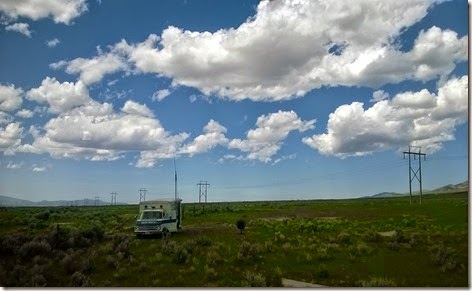
With a little more walking around, we discovered we could drive the van right up to it, so… We did! You can barely see the arrow in the sagebrush in the middle of this photo. Looking sound toward the arrow:

WP_20140526_008

WP_20140526_007

The purpose of the trip was to check our equipment, so we did a fair amount of work setting up and powering up radios. As you can see, we had a Buddistick supported on a mast on the side of the truck.

WP_20140526_006

Once we had that tuned up, we were easily copyable into North Dakota, St. Louis, and California at 100 watts. With my 817 at 5 watts, we had a clear-as-a-bell QSO into Washington State (Spokane). Overall we were quite pleased with the site and the equipment, although there are some take-aways that we need to work on.

WB6YOK working contacts on 20m with a Yaesu FT-897:

WP_20140526_005

Some additional photos:

Looking NE over the arrow. The orange piece sticking up in the lower corner of the arrow is the foot for the steel tower that sat on top of the arrow. This photo was taking from inside of what once was a cabin next to the tower – it appears they had two generators installed in the cabin.

WP_20140526_011

Looking at the hills to the east:

WP_20140526_013

Standing on the arrow, looking toward the north:
WP_20140526_012

We have a ton of stuff to do to get prepared, but we’re really excited about the trip. Hope you can join us over the bands!

Thursday, May 15, 2014

K7JTO: What's Comng

It's been quite some time since finishing my PFR3. And that coincided with work really picking up, so I have been slammed in my life. I've not been out to operate on HF, at all, and barely even on VHF. Good news though: my buddy WB6YOK and I are putting together plans for a local mini DXpedition. We are tentatively looking to activate an old airmail direction arrow north of Salt Lake City. We should be operating Thursday through Saturday noon the week after the 4th (July 10-12). We'll be putting plans together shortly and hope to have some big announcements to make soon.

My main goals:
- operate CW. I completed the CWOps Club class and have hardly touched a key since, so I need to burn some midnight oil between now and July to get my listening skills back. I'd like to leave the weekend copying and sending > 15 wpm and then keep it there by operating weekly
- operate SSB and digital (PSK)
- experiment with a variety of antennas, including a kite antenna
- kit up a couple project radios and make some QRP and QRPp contacts
- one of these projects is a Rockmite I can take when I travel, so I can do CW while on the road
- order and build a 20m QRPp rig, probable a Hendricks or a new Rockmite ][
- run and use WSPR on a Raspberry Pi, to check out propagation
- shoot the breeze with Chuck and anyone else who shows
- I have been wanting a contact from India, so I'm hoping to get that contact on the DXpedition.
- build my SSB and CW contesting skills 

Chuck's got a massive delta loop antenna he built for a Pony Express commemorative station a few years back when I first met him, we'll be using that as our primary antenna for QRO HF ops. Hopefully that monster will pull in Asia. I'll also be putting my Buddistick to use, and checking out (maybe building) a series of other backcountry EFHW and dipole antennas. We'll have a couple video cameras on site as well, and so you should actually see some activity on my YouTube channel. We are hoping to have Internet access and to keep folks up to date via Twitter--we'll see about that.

Want to know more about the arrows? Google "airmail direction arrows" to learn more. We'll maybe have a few write ups and stuff at some point, so keep checking here.

Wednesday, February 26, 2014

PFR3: Build Complete


I finally finished building the rig about 10 days ago. What an adventure! I last left off having completed Group 2 and started on a group 3. Finishing group 3 was actually pretty straightforward: wind and install a bunch of torroids, and solder in a few more components to complete the transmitter and BLT tuner. The only really tough aspect was winding the monster torroid in the transmitter. Wow--3 interleaving windings, with heavy gauge wire. More on that later...

Recycling an old photo of the board, let me assure you of one thing: random lead clippings that short pins on the programable chip can be quite annoying. I must have re soldered 10 different components before I saw the lead clipping laying there. Assemble, disassemble, reassemble, disassemble... That cost a good 20 minutes. But finally I have the main board complete!


Next, it was time to kit the box. The instructions recommend not kitting until the rig has been fully tested. In retrospect, that makes sense... sigh. Here's how it looks now that it's kitted, though!

The circuit board mounts into the top of the case, with 4 screws which seem to provide ground. That will become important shortly... Kitting everything was pretty straightforward, although I was surprised that the power tap didn't fit. I had to ream out the hole just a bit (nothing a really sharp tempered steel knife couldn't handle). Remember the comment about the external power? Well, if you look really close you'll see I connected the center pin on the external power jack to the ground (white lead), and the outside of the jack to the board's power. Yes, I'm sure you did the math and arrived at the conclusion I overlooked: this causes a short and can really heat up a battery quickly. I'm actually lucky I tested with 8 AA's at 12v rather than a larger 12v SLA battery that could have delivered a bigger punch!


The internal battery pack has sticky tape on it. It needs to be soldered to a wire. This is one of two complaints I have about the entire kit: the plastic battery case melts before the contacts are warm enough for the solder to flow. (My other complaint is about the documentation on T1 and on the monster torroid.) You can barely see it my workaround, but I ended up soldering to the spring inside the battery pack (topmost row, on the far right).


This is the rig, no decals yet. That yellow color is pretty bright--selected to help you find or avoid stepping on the rig while operating in the field.


Connection points. From left to right: power, BNC antenna, switch from BNC to balanced line, and balanced line contacts.

Well at this point I'm pretty happy. My buddy WB6YOK and wrapped up around 10:30 Saturday--another quite long evening and I know my wife will be happy when I'm done disappearing for half a day at a time. I know I will be!


Evidence: it runs on external power. It runs on internal power. It runs!

My preliminary testing was indeterminate--lower power reading on the SWR/power meter, but the antenna was poorly tuned. My Elecraft T1 tuner showed 5+ watts on 40 and 30 (the tuner has LEDs to indicate 1, 5 and 10 watts, so if the rig puts out 4.5 watts it's still not possible to know anything other than the righ puts out more than 1 watt). More testing yet to be done.

Next steps:
1. More output testing: I'd like to buy a few $0.50 50 Ohm resistors, build a dummy load, and test on a matched "line".
2. Install decals
3. Clear coat
4. I'm toying with spraying some reflective clear paint I have on various spots around the rig, to aid discoverability during nighttime
5. I would love to find some small rubber "covers" to put over the 4 switches. The rest of the through holes are actually sealed, but these 4 aren't. We swapped out cable boxes recently, but kept the old remote and it has a few rubber covers which just might work.
6. Build a balanced line and test the BLT
7. QSO! 

I broke this out a couple days ago and tuned around the bands. I was swapping back and forth between my 817 and the PFR. I got a report later from a ham in Oregon that he'd heard me call CQ on 40 but he couldn't get his rig set up in time to answer me (I QSY'ed a bit too quickly). I don't know which radio I was on at the time). 

Between the dummy load and figuring out the "recipe" for my Buddistick, I think I'll have this dialed in shortly.


Saturday, February 1, 2014

PFR3 Continues

Just an update: successfully finished group 2, all tests passed (although due to some unplanned massive remodeling at my buddy's, we couldn't get the oscilloscope out). Happy happy! So of course, I soldiered on and started group 3, which begins with a few soldered components and then a pretext. It was on the protest that I completely fell apart. The mistakes?

1. There are two "U8" markings on the board. Pins 1 and 13 are supposed to be at zero volts with the power on and the rig in straight key mode, then 1.2 volts with the key closed. Odd, I was seeing 4 volts on pin 1. Oops... Wrong U8. On the correct U8, I see 0 volts with the key opened and 2 with it closed. The group weighed and said 2 volts is fine--less important the voltage vs. the fact that the circuit is open or closed.

2. Wrong resistors. As I posted to the reflector:

* Manual R6 & R7 should be YEL/VOL/YEL
* Errata: ORG/ORG/YEL
* Installed: YEL/VOL/YEL

Which is right? The errata and the manual agree on 470k, which is YEL/VOL/YEL. Press onward.

3. While troubleshooting the voltage issues, I literally went back to the beginning and checked every single component. Oops, I installed the wrong captor C24. Desoldering, replace, resolder in C56. Oh, whoopsies... Omitted R35 (I remember now I couldn't find it on the board when I was doing stage 2, and apparently I forgot to look again).

Needless to say, I have now checked every component, looked at every solder joint, and made sure everything works. Finally, time to press forward wih L7 to finish the transmitter, so I can start the BLT.

Lessons? Go slow. Mark your questions. Pay very close attention to markings, esp on your caps. If you're tired, stop--rushing won't get it done sooner.

I cannot wait till this is done, if only to put my quirky tom-foolery behind me!


The blue cap on the right side, next to the LCD? Yah, it goes about 5 o'clock from the Dove treat (my wife is the best!). You can see the big trace, right next to the little yellow 104 cap.

See the LCD display? See the conspicuously large resistor spot traced out in white marking, much like a victim's profile at a murder scene? Yah, I don't know how I missed it either!

See the vertical chip just next to the Dove treat? That's U8. Oh, but wait--see the other U8, just below the LCD. Hello, I'm Daryl. This is my brother, Daryl and this is my other brother Daryl. No offense to the boys at Hendricks. I'm sure this is my careless reading of the manual and/or errata. I've made enough dumb mistakes to prove them the experts! And hey, every problem is an opportunity to learn!